Flow Monitoring Processes

flowmonitoring.png

Since 1998, V&A has supported municipalities and agencies in managing their water and wastewater collection systems and mitigating sanitary system overflows.

V&A’s primary responsibility to our flow monitoring clients is to provide quality data so they can execute smart decisions for their investments. We understand that decisions are crucial for future multimillion-dollar CIP construction efforts and flow monitoring data plays an important role during this process. There are distinct features that separate our data collection processes from other firms.

  • Committed Personnel
    Our dedicated engineers are “hands-on” and spend much of their time in the field. Better continuity from the field to data analysis makes for better final reports. 

  • Comprehensive Data Collection
    Our team stands out in the marketplace because the engineers direct the work from the beginning to the end and, therefore, we guarantee data integrity. Through good accurate data, we are capable of pinpointing predictions of peak flows for a given segment of the system and establish valuable hydraulic models.

  • Project-Specific Technology
    Since V&A is not affiliated with any particular manufacturer, equipment diversity provides a meaningful advantage in determining the proper flow metering technology to match project-specific hydraulic conditions. 

  • Quality Reports
    We are committed to producing detailed, high-quality reports to achieve our client’s goals and would be happy to provide samples to compare against our competition. 

  • Data QA/QC
    Our QA/QC operating standard procedures is a combination of checks and balances to ensure our clients are receiving the utmost accurate data collection and reports. A few of the techniques include reviews for potential sensor drift (Figure 5), scatter plots analysis (Figure 6), and Manning’s curves comparison charts (Figure 7).

Figure5.png
Figure6.png
Figure7.png


40 years and counting!

40th anniversary-04.png
Poseer un negocio. English translation: Own a business. Words of my mother since I was 6 years old. I always knew my work would fill a large part of my life and it does. I love that.
— Jose Villalobos

In 1979, our founder, José Villalobos, felt there was a need for an experience-based engineering firm that prioritized client service. His original services included corrosion engineering, civil engineering, and industrial waste treatment. He found that he could differentiate the firm by focusing on corrosion engineering with a specialty in evaluating, rehabilitating, and preserving municipal infrastructure. The first office opened on Commercial Street in Palo Alto, California and our clients included many cities, special districts, and contractors in the Bay Area. By 1982, we moved to a larger space in the historic Old Alvarado Hotel in Union City. In 1987, further growth prompted another move, to Oakland, where our corporate headquarters remain. Providing a valued service to the market allowed for our expansion to other cities – Houston, Texas; San Diego, California; Las Vegas, Nevada. This year marked the opening of offices in San Antonio, Texas and Lakewood Ranch, Florida where we will continue to offer our specialized services to both existing and new clients. 

When hiring that first employee in 1980, we knew that creating a fulfilling and supporting environment for our staff would be critical for the success of the firm. Our early company foundation notes included a pledge to create a firm where engineers can enjoy challenging work and grow their expertise; and have a fun and engaging work environment. Our dedication to our employees continues to this day with a commitment to a strong company culture grounded in our core values of honesty, integrity, respect, commitment, loyalty, and quality. 

One of the most rewarding things about being in business for 40 years is the strong relationships we have built with our clients over those years. We are working together to improve our communities and to protect public health and the environment. As our infrastructure ages and new challenges arise, we look forward to the continued partnerships. We are proud of this milestone anniversary and look forward to what we will learn in the next 40 years! 

Looking back . . . José Villalobos

Looking back . . . José Villalobos

Corrosion Engineering for Transit Systems

transitphotos-01.png

Electric Street Cars date back to the 1880s when the Richmond Union Passenger Railway successfully tested the first electric train in the United States. By the early 1900s, electric rail cars experienced a rapid expansion. Today’s light rail transit (LRT) systems provide an economical method to reduce traffic congestion. 

Most LRT systems are powered electrically. Substations with DC (direct-current) rectifiers supply electricity to the train through an overhead cable via a trolley or a pantograph. It was quickly realized in the early days of DC transit systems that both the transit utility structures and nearby buried utilities were experiencing rapid corrosion and premature failures. These failures were due to stray currents that followed an unintended path. Current passing through the motors in a train are intended to return to the substation via the rails. However, current can get off the rails and once in the earth, the current may take many paths, including nearby metallic pipelines. Stray current (sometimes called “leakage currents”—i.e., unwanted, non-designed currents) can cause rapid corrosion of buried utilities near transit systems. Stray-current corrosion occurs at the point where the current leaves the pipeline.

Utility owners that have buried utilities in the vicinity of DC transit systems should be aware of possible stray current corrosion that may be occurring on their pipelines. The best defense against stray current corrosion is making sure the transit system owner maintains their system and the utility owner does pipeline testing to verify if they are experiencing stray current corrosion.

The agencies we have worked with include Santa Clara Valley Transportation Authority (VTA), the Bay Area Rapid Transit (BART), Sacramento Regional Transit, San Diego Metropolitan Transit System, Long Beach Transit, Denver Regional Transit District, Utah Transit Authority, and the Houston Metropolitan Transit Authority.

Our scope of work includes the design of stray current mitigation and testing systems, construction acceptance testing, testing during pre-revenue operations, establishment of maintenance programs, working with utility owners to mitigate stray current corrosion, and training of transit personnel to enable the transit agencies to perform long-term maintenance.  

For over 25 years, V&A has worked with transit districts and utility owners and completed multiple transit corrosion engineering projects totaling over $1M in fees. Our corrosion engineers are familiar with transit systems and the consequences of stray current corrosion.

transitphotos-03.png

The Partnership Between Cathodic Protection Design and Soil Resistivity Testing

VA_June-16.png

Soil resistivity relates to an increase in corrosion activity and therefore dictates the type of cathodic protection designed to protect metallic structures found in various environments. Common applications for cathodic protection are steel water or fuel pipelines and steel storage tanks; steel pier piles; ship and boat hulls; offshore oil platforms and onshore oil well casings; offshore wind farm foundations and metal reinforcement bars in concrete buildings and structures. 

And how do we test the soil? In-situ soil resistivity testing is performed using the Wenner 4-Pin Method in accordance with ASTM G57. This test method involves the use of four metallic pins driven into the soil in a straight line at equidistant spacing. A ground resistance tester is used to discharge alternating current into the soil from the two outer pins. The current creates a voltage gradient in the soil proportional to the average resistance of the soil. The voltage drop between the two inner pins is measured, and the resistance of the soil to a depth equal to the pin spacing is calculated by the meter using Ohm’s Law. This gives us a snapshot of the level of corrosion beneath the surface, guiding us to the best Cathodic Protection design.

San Jose-Santa Clara Regional Wastewater Facility Yard Piping Condition Assessment

Project Description 

V&A performed condition assessments of process piping in support of the Yard Piping and Road Improvements Project (Project) at the San Jose-Santa Clara Regional Wastewater Facility (RWF). The purpose of the assessments was to obtain physical condition data on buried piping assets so that rehabilitation design and prioritization can be performed by the City of San Jose’s Environmental Services Department (City) and Black & Veatch Corporation (Black & Veatch), who serves as the Owner’s Advisor (OA) for the Project. V&A also helped establish a baseline for data collection, interpretation, and reporting for future Yard Piping assessments on the Project. 

Condition assessment methods used to evaluate the piping included visual assessment with photo and video documentation, closed circuit television video (CCTV) with hydro-jet cleaning, lining assessment, concrete sounding, concrete penetration measurements, surface concrete pH testing, surface penetrating radar, and concrete coring. Due to the crown corrosion from biogenic corrosion that was observed, V&A also took dimensional measurements to help quantify the extent of damage.

The results of the field investigation were analyzed and utilized to develop overall pipe condition ratings. Pipe condition ratings were based on a scale between 1 and 5, with 1 being new or excellent condition and 5 being failed or imminent failure. These ratings were used to estimate the remaining service life of the piping as well as to help prioritize repair and rehabilitation needs.

Assessment, Design and/or Construction Challenges and Solutions

V&A prepared a safety plan to mitigate risks and to outline procedures to be implemented during confined space entry work related to the Yard Piping Condition Assessment at the RWF. As with all projects, safety is of the highest priority and is an integral part of our work. V&A’s confined space trained engineers conducted the field investigations with onsite confined space entry and rescue support from Lee & Associates Rescue, Inc. (LAR) and/or Jamison Engineering Contractors, Inc. (Jamison).

In order to ensure consistent data collection and reporting on the project going forward, V&A worked closely with the Black & Veatch and the City to develop a pipe rating index system based on the National Association of Sewer Service Companies (NASSCO) Pipeline Assessment and Certification Program (PACP). The pipe rating index system allowed V&A to assign defect grades and overall pipe ratings to individual pipe segments, and ultimately correlate the ratings to an estimated remaining service life.

The Way to Effective Odor Control

Chocolate chip cookies. Fresh cut grass. The ocean breeze. Each of these scents likely invokes a specific feeling or memory. Neuroscience tells us that the sense of smell is strongly linked to memory and emotion, probably more than any of our other senses. Our perception of odors as good or bad depends as much, if not more, on how we feel about past events associated with the memories these odors trigger as it does on what it actually smells like.

Odor complaints can often be one of the most perplexing problems when operating a wastewater system, due to their subjective nature and seemingly unpredictable pattern. A positive experience in how the odor complaints are handled will leave a lasting impression on stakeholders and operators alike. Having a well-structured procedure for documenting and investigating odor complaints is necessary to effectively manage these issues.

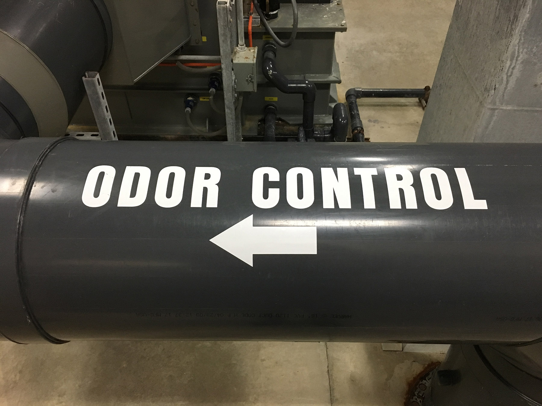
There are a number of considerations that may influence the scope and size of an odor control strategy, including regulatory requirements, corrosion concerns, and the desire to be a good neighbor. Clearly defining the goals of an odor control program is key to developing the most straightforward approach to mitigating odor emissions. Seemingly unrelated odor and corrosion issues are often influenced by a few key contributors that result in systemwide problems. Identifying the most effective odor control strategy requires a prioritized approach to eliminating the low hanging fruit and mitigating odor emissions across the entire system.

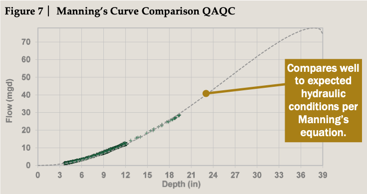
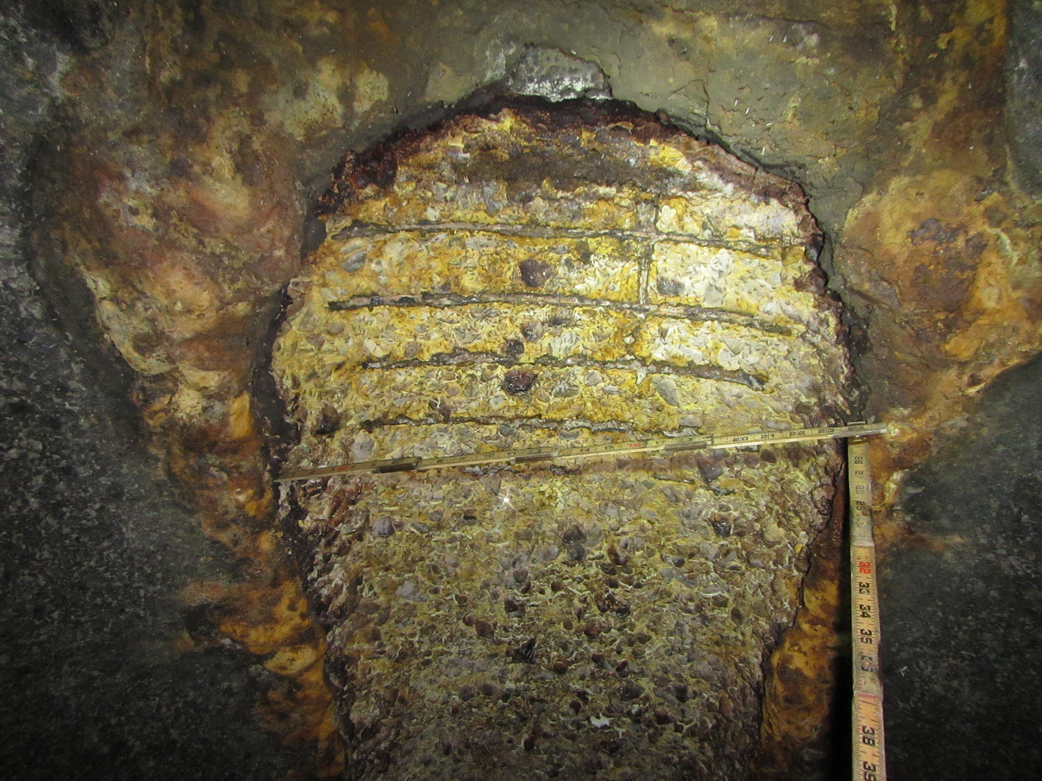
V&A uses a variety of tools to identify and characterize odor issues, including hydrogen sulfide and differential pressure monitoring, odor sampling, and ventilation and air dispersion modeling. Hydrogen sulfide is one of the most common parameters evaluated as it a good indicator of the source of both odor and corrosion issues. It is easily monitored, influences the technology selection and operating costs of most odor control solutions, and its generation rate can be incorporated into hydraulic models to compare alternative solutions and determine the impact of future infrastructure changes on the systemwide odor conditions.

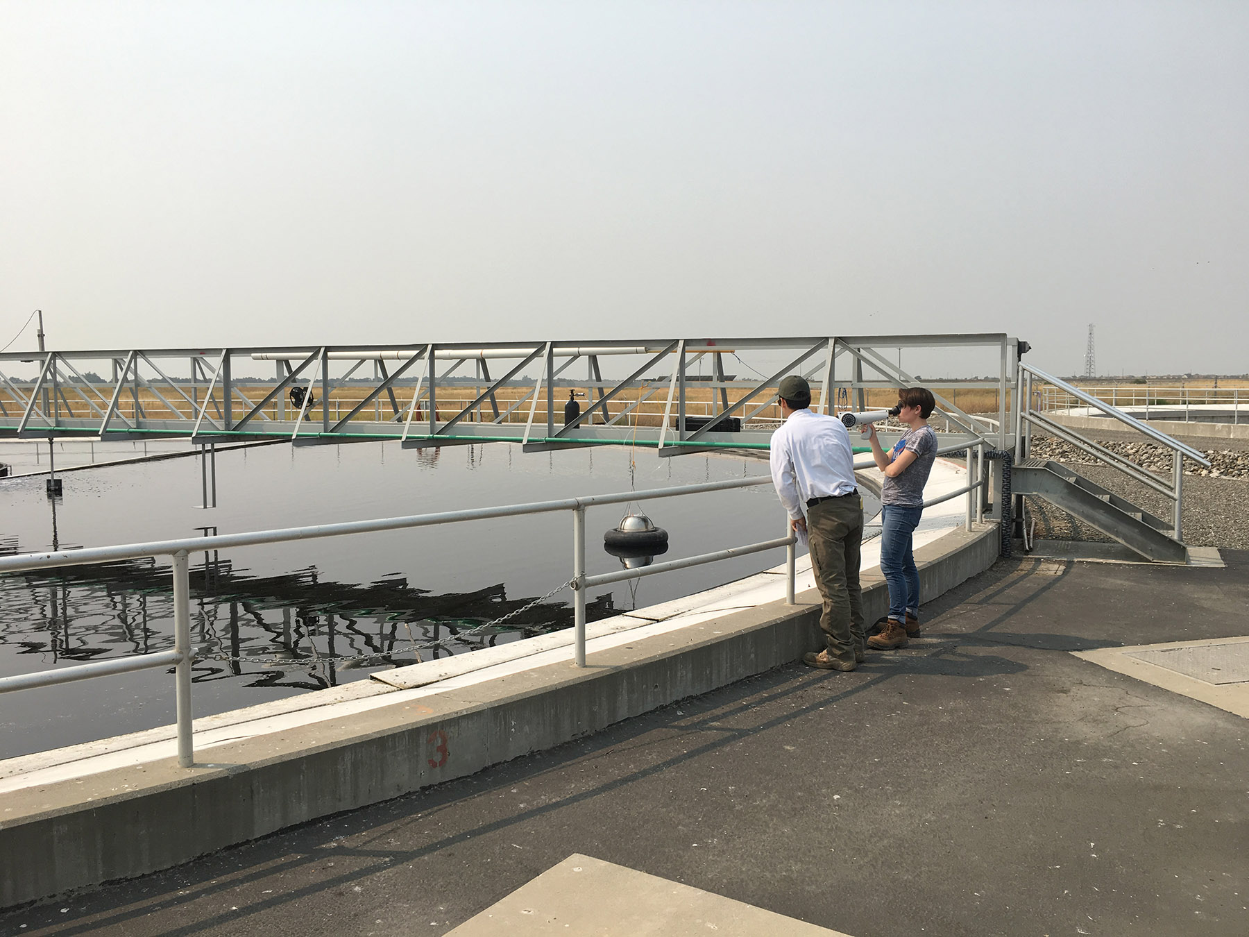
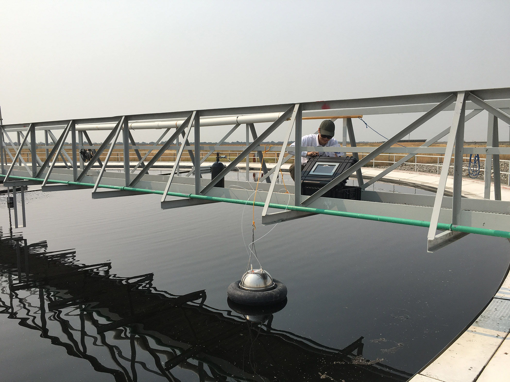
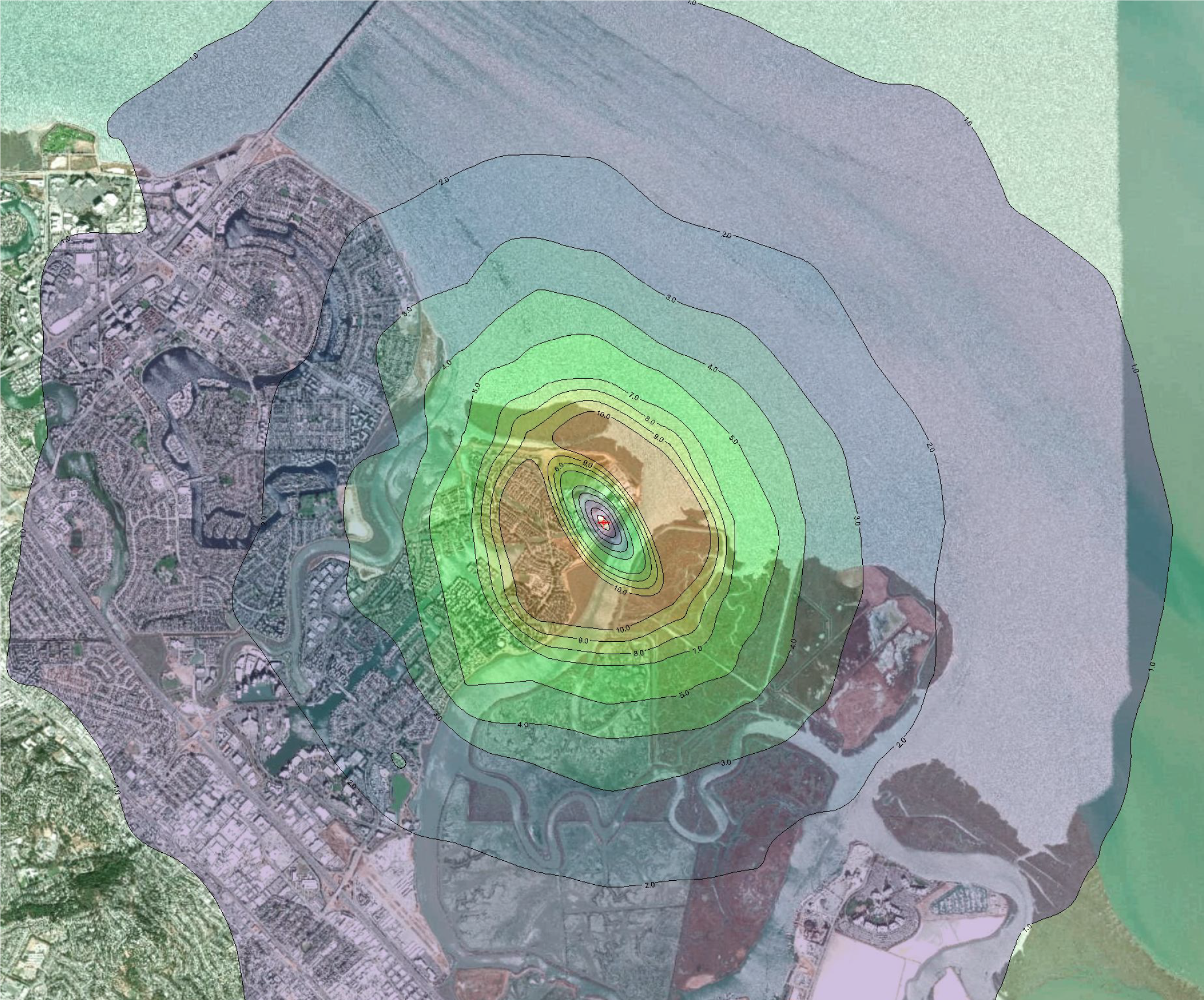
Quantifying odor complaints beyond subjective terms such as “terrible” or “unbearable” is important to monitor the effectiveness of the odor control strategy. Olfactometry measurements provide a repeatable and quantifiable basis for investigating odor complaints and comparing the relative “strength” of different odor sources. Once the odor concentration is known for a given odor source, V&A uses air dispersion modeling to determine the likelihood that odor emissions are migrating offsite, understand how future infrastructure upgrades may change the odor conditions, and identify the required odor removal performance to meet the odor control objectives.

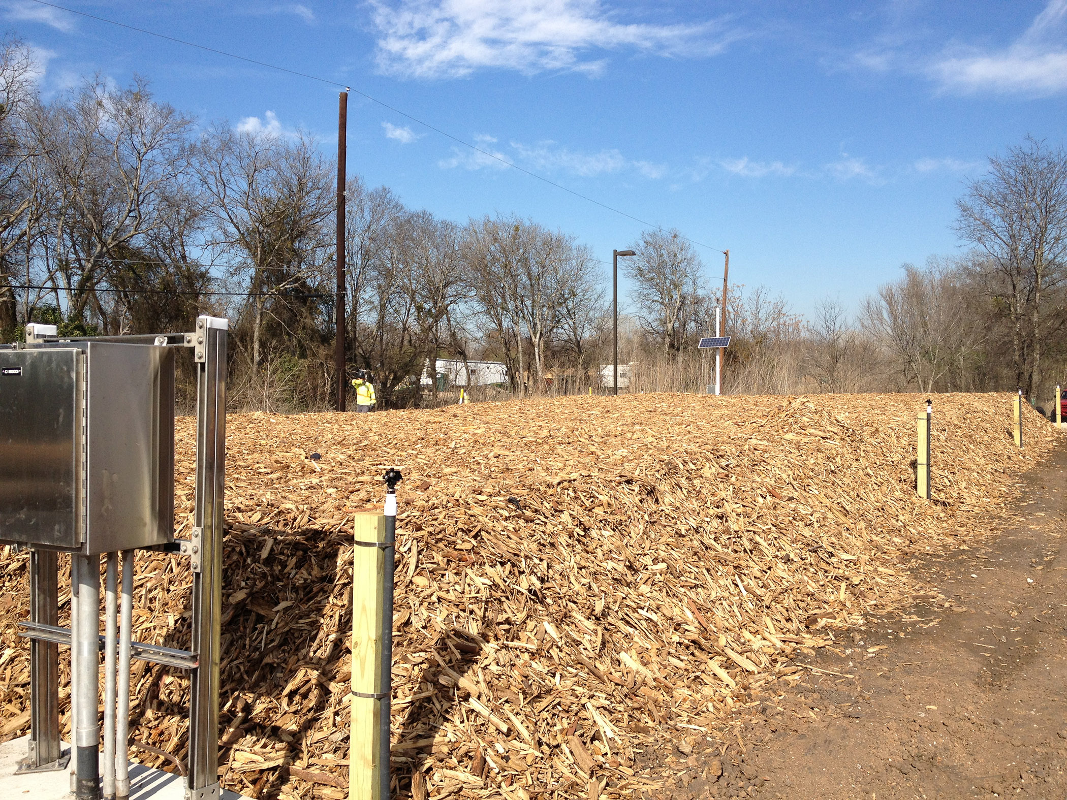
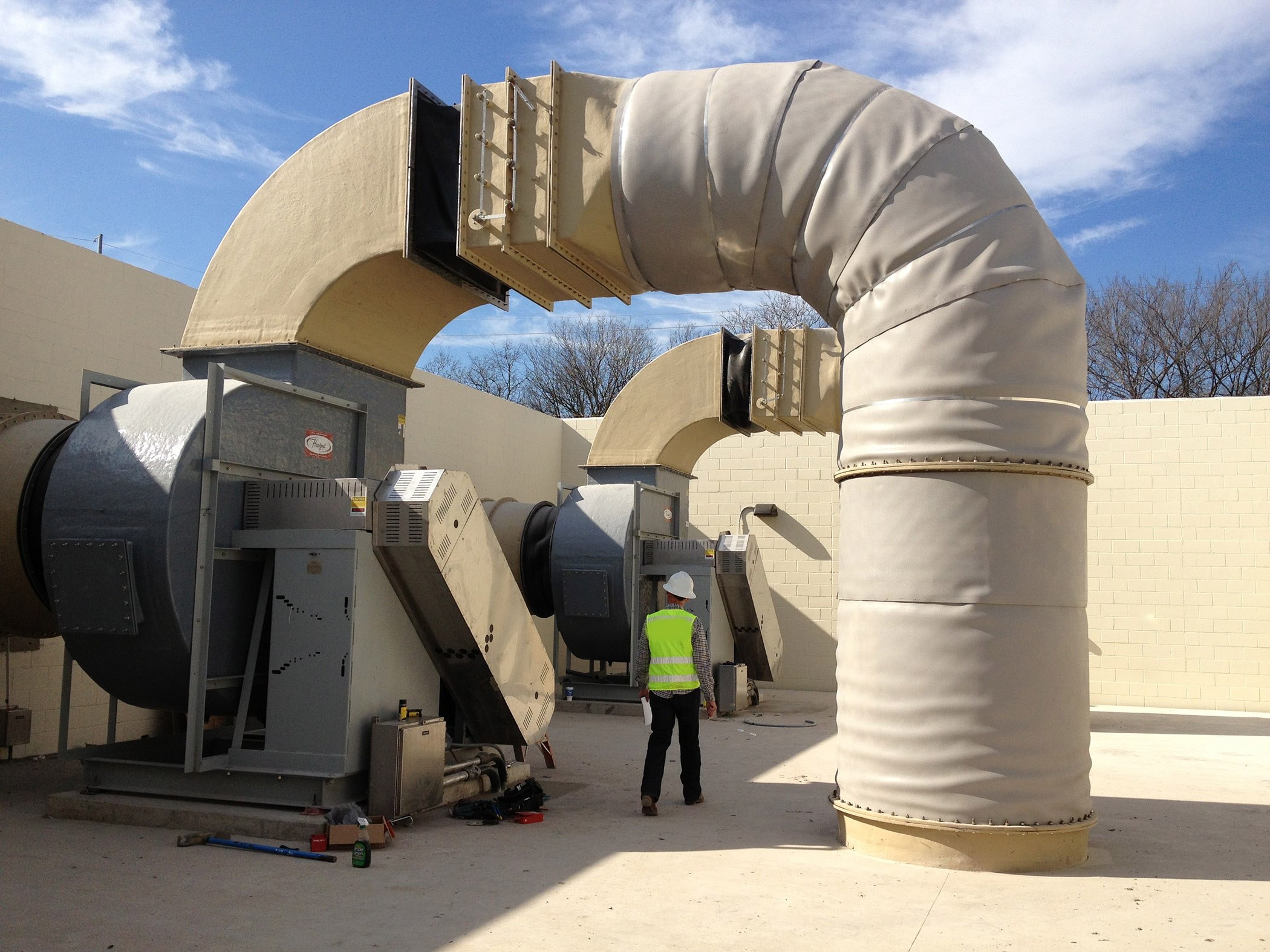
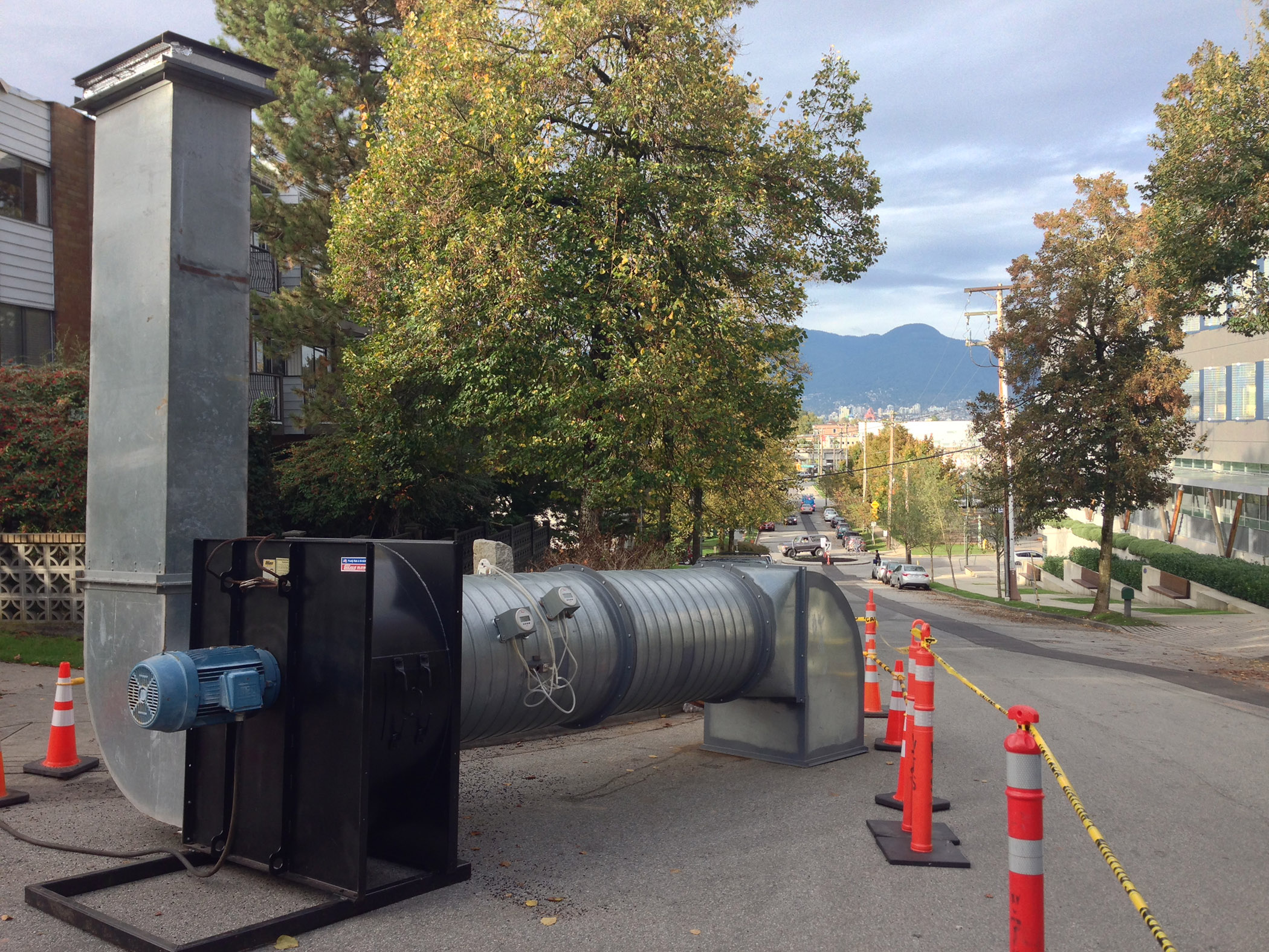
Vapor phase odor control is an effective means of treating odors from a variety of sources in a centralized system, even in large collection systems. Using the latest advances in biological odor control, high hydrogen sulfide and odor loading sources can be effectively treated in a sustainable manner with minimal operating costs and little or no chemicals. V&A uses sewer ventilation modeling to determine the capacity for airflow within collection systems, and fan testing to determine the viability of vapor phase treatment systems. Combining hydrogen sulfide and differential pressure monitoring, fan testing involves extracting known quantities of air to simulate the effects of a permanent odor control facility. V&A has used these methods to effectively size and locate vapor phase odor control facilities within wastewater collection systems from 100 cfm to over 40,000 cfm in capacity.

It is important to remember that there is not always a clear path to effectively addressing every odor complaint in a wastewater system. It often requires an iterative approach of identifying the most significant contributors, implementing the appropriate solutions, and evaluating how effective these solutions are at meeting the odor control goals. A comprehensive odor control strategy that includes investigation, evaluation, and implementation will ensure that you are headed in the right direction and enable you to set realistic expectations for your stakeholders within the available funding mechanisms.